
Dorman conduct tite on off led toggle switch. 4 pin relay wiring diagram.
39 4 Pin Starter Relay Wiring Diagram Wiring Diagram
Not just will it assist you to attain your required outcomes faster, but in addition make the whole process.
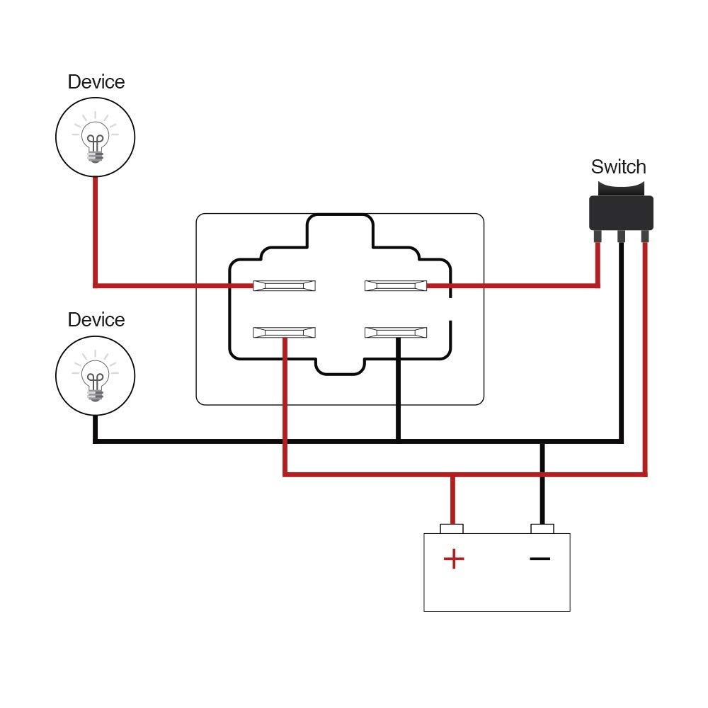
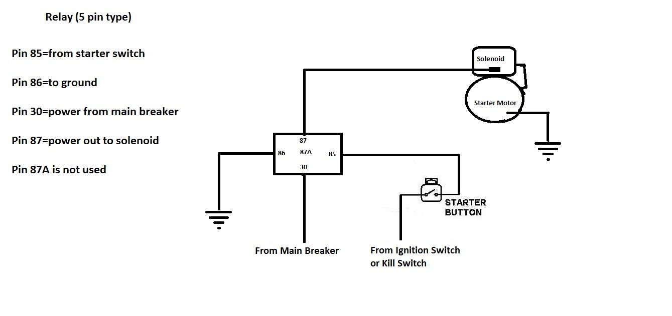
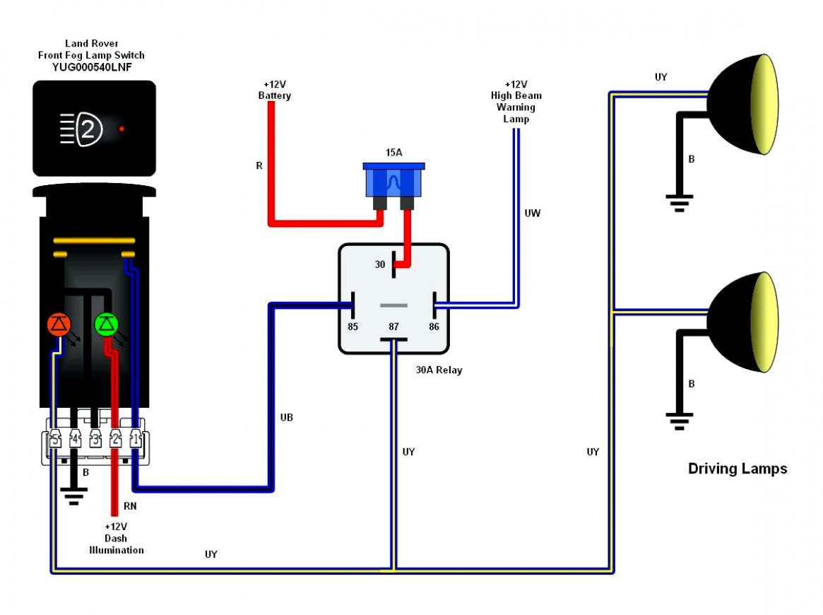
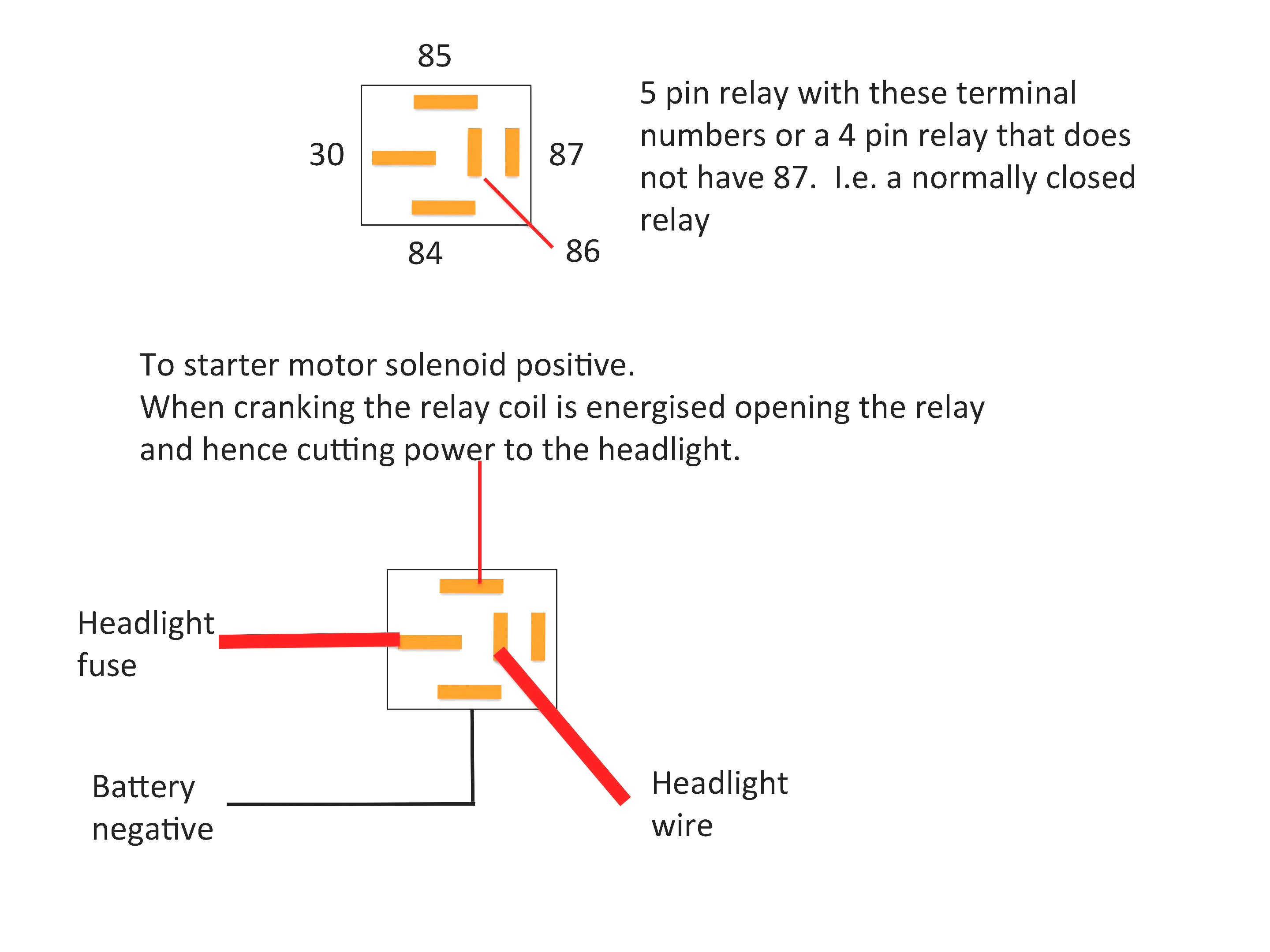
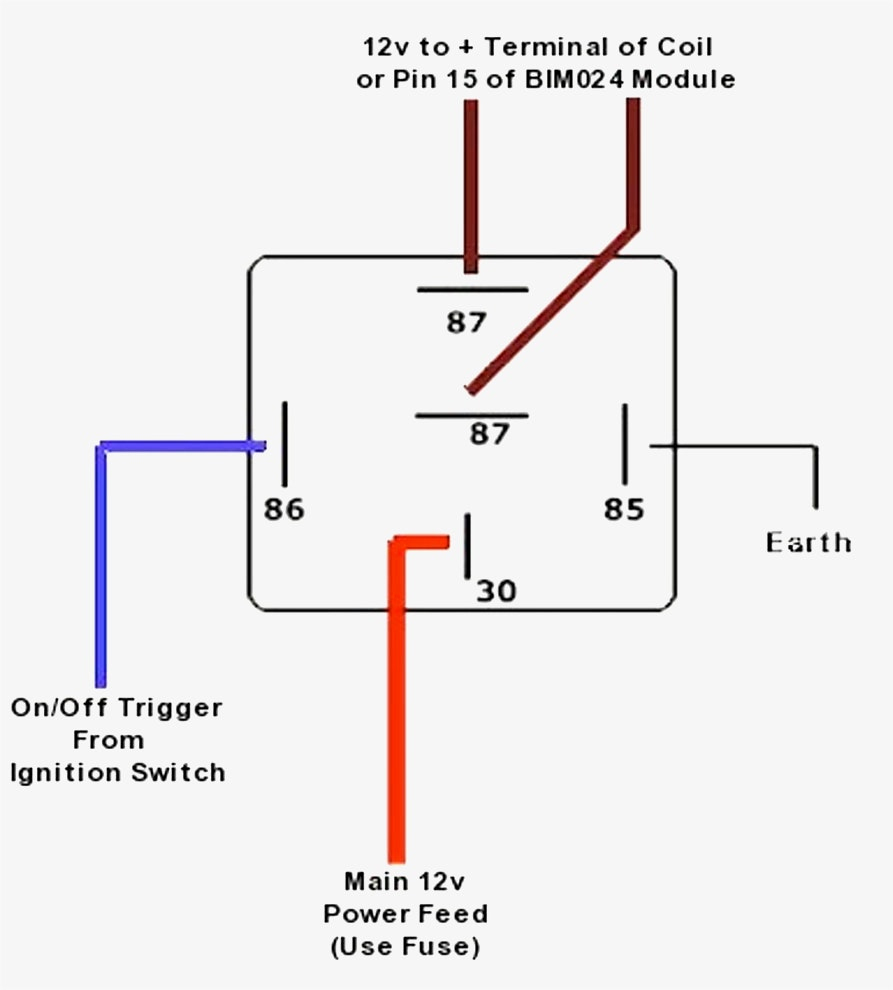
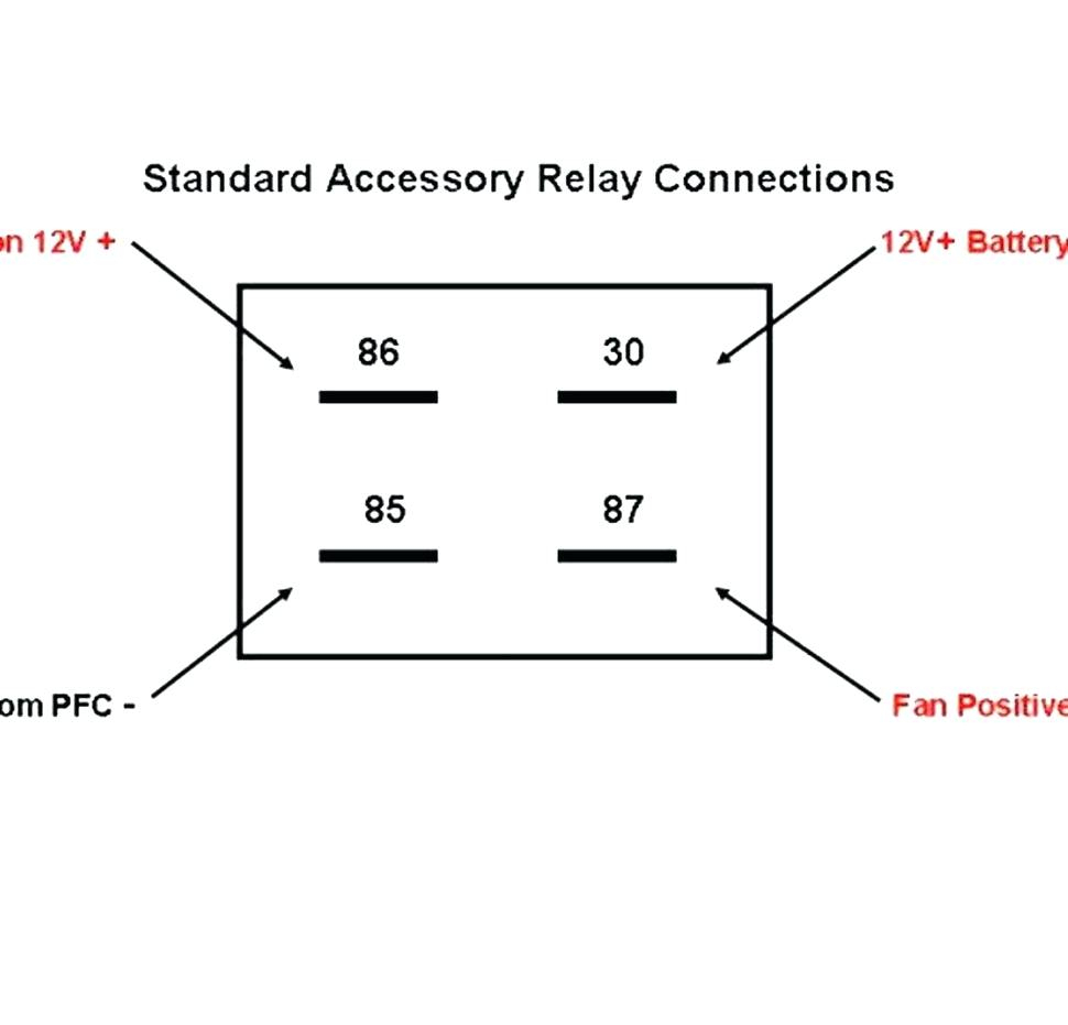
4 pin relay diagram. In the 5 pin relay wiring diagram below, i show how to turn on lights when the relay is activated and how to turn them off when the relay is deactivated. This is a typical wiring diagram for a standard relay installed for headlights, horn, fuel pump, electric fan, etc. 4.7 5 pin relay wiring diagram for lights.
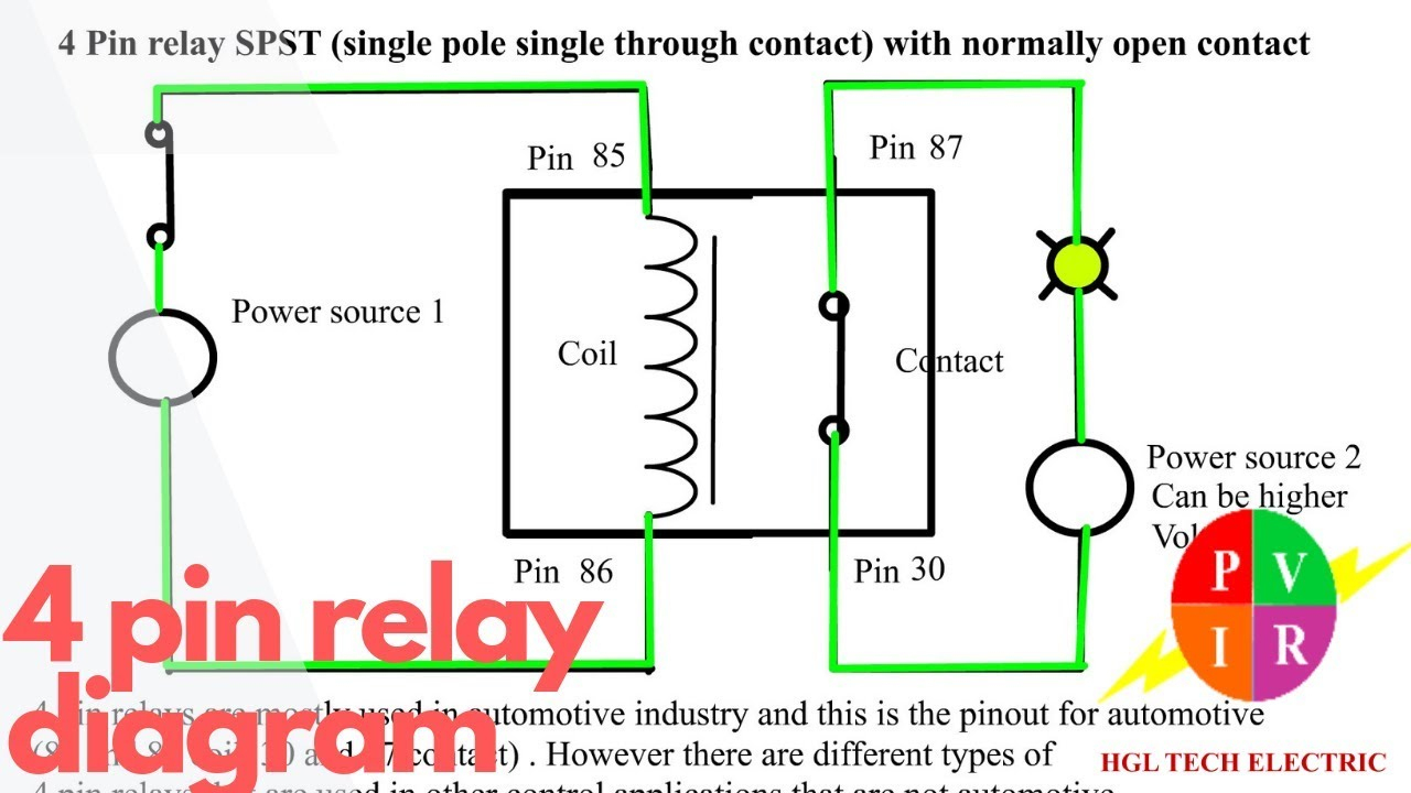
When the relay is energized (on), pins 3 and 5 have continuity. A relay is typically used to control a component that draws high amperage. When the input current flows through the copper coil, the magnetic field is generated and the.
4 pin flasher unit wiring diagram it also will feature a picture of a sort that might be observed in the gallery of 4 pin flasher unit wiring diagram. Toyota 4 pin relay wiring diagram. A wiring diagram usually gives instruction just about the relative direction and covenant of.
With this kind of an illustrative guidebook, you'll have the ability to troubleshoot, stop, and total your projects with ease. 5 pin is compromised of 3 main. If not, the arrangement won't work as it ought to be.
It shows the components of the circuit as simplified shapes, and the capability and signal connections in the midst of the devices. Also, you will again hear a clicking sound and those two wires are for the relay coil circuit. So a single pole double throw has a.
Similarly, if you want to control or wire a fan with a. Wiring diagram for a 4 pin relay wiring diagram is a simplified agreeable pictorial representation of an electrical circuit. 4 pin relay wiring diagram horn.
Relay can be the best option to control electrical devices automatically. Simply check out the relay wiring diagram 4 pin to understand the correct wiring. Components of 4 prong relay wiring diagram and some tips there are just two things that will be present in almost any 4 prong relay wiring diagram.
Wiring diagram for a 4 pin relay wiring diagram is a simplified agreeable pictorial representation of an electrical circuitit shows the components of the circuit as simplified shapes and the capacity and signal connections with the devices. A circuit is usually composed by various components. It shows the components of the circuit as simplified shapes, and the capacity and signal connections with the devices.
5 pin is compromised of 3 main. The other thing which you will see a circuit diagram could be traces. August 23, 2021 · wiring diagram.
Four pin relay basics and working animation. There are different kinds of relays for different purposes. The first element is symbol that indicate electric element in the circuit.
What is a 4 pin relay and how does it works. The relay allows full power to the component without needing. The stock came with a single horn.
These instructions will likely be easy to comprehend and use. From left to right on the pins. It can be used for various switching.
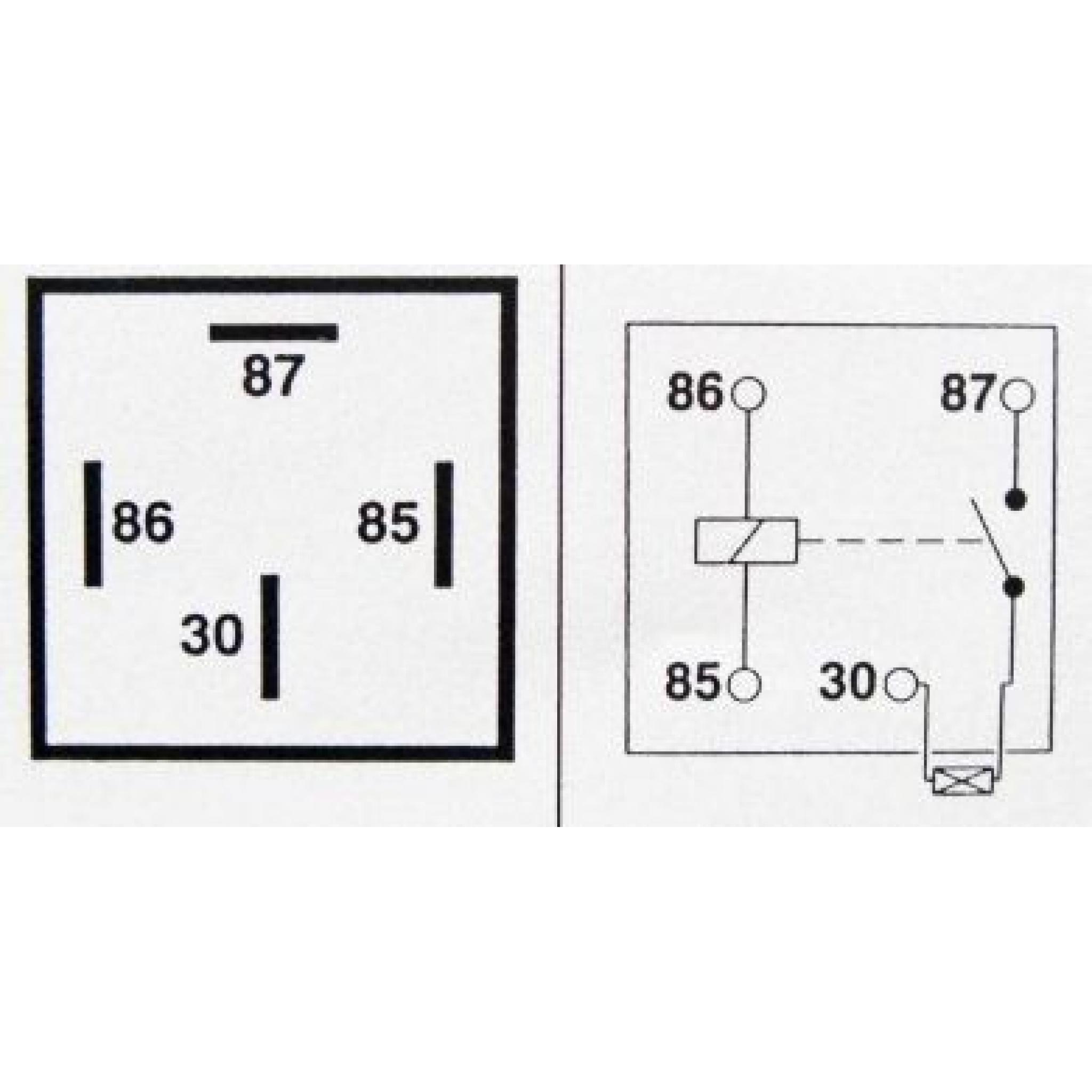
Bosch 4 pin relay wiring diagram. The coil circuit's two terminals are 85 and 86, in which terminal 85 is the relay's coil negative contact, and terminal 86 is the relay's coil positive contact. Four pin relay basic operation.
With this kind of an illustrative guide, you are going to have the ability to troubleshoot, prevent, and total your projects easily. Automotive f relay 40a spst mgi sdware how to wire a 4 pin step by guide diagram horn light evshunt waterproof 80amp 87a 5 87 led sho malaysia and socket harness. The relay is an electromagnetically operated switch, where with a low level input current, typically in the range of 100 ma and 150 ma, can be switched high level current up to 80 a, in some cases and more.
The diagram above is the 5 pin relay wiring diagram. You can simply be able to identify the colic circuit by simply attaching one after the other two wires together with the positive and negative posts of the battery.
Simple 4 Pin Relay Diagram DSMtuners


Bosch Relay 12V 30A Wiring Diagram Wiring Diagram And
SPST 4 Way 40A 12V Relay Wiring PinOut Diagram OBD

12vdc Relay Wiring Diagram 4 Pin Relay Wiring Diagram Horn

4 Pin Relay Diagram 12 Volt Car Relays Used In

50 Ford 4 Pin Relay Diagram Wiring Diagram Plan

Stage 4 Complete Beginner's Guide For Arduino Hardware
Bosch 4 Pin Relay Wiring Diagram Cadician's Blog
4 Prong Relay Wiring Diagram Wiring Diagram

Diagram by Akita Your Diagram Source from Akita. Relay

Bosch 4 Pin Relay Wiring Diagram Cadician's Blog

[DIAGRAM] Spotlight Wiring Diagram 4 Pin Relay FULL
Relay 4pin 12v 30A Fused Automobile Relay Wire Car Auto
4 Pin Relay Wiring Diagram Cadician's Blog
4 Pin Relay Wiring Diagram Wiring Diagram

[DIAGRAM] Spotlight Wiring Diagram 4 Pin Relay FULL

4 Pin Relay Wiring Diagram Lights Electricity
Bosch 4 Pin Relay Wiring Diagram Cadician's Blog

Relay Wiring Diagram 4 Pin Wiring Diagram And Schematic