Yamaha Xs850 Wiring Diagram

Rj11 Socket Wiring Diagram Australia, How to punch down an RJ11 Telephone Jack, 6.36 MB, 04:38, 387,634, CableSupply.com, 2009-08-05T00:16:...

Tuesday, October 25, 2022

Vag Wiring Diagrams

Vag Wiring Diagrams

Rj11 Socket Wiring Diagram Australia, How to punch down an RJ11 Telephone Jack, 6.36 MB, 04:38, 387,634, CableSupply.com, 2009-08-05T00:16:07.000000Z, 19, Rj11 Socket Wiring Diagram Australia | Computacion, Redes de computadoras, Computadoras, www.pinterest.com.mx, 728 x 783, jpeg, rj11 wiring rj45 diagram cable ethernet usb jack pinout adapter cat5 female male convert using rs485 cat wires code socket, 20, rj11-socket-wiring-diagram-australia, Anime Arts

Here is a quick reference chart for the color abbreviation of wires used in the vag group vehicles. This maybe common knowledge for many. And some may have never seen the english (bentley) wiring diagram color abbreviations, so here they are. In 1937, volkswagen was founded, which was to become the symbol of the new germany.

1998 vw mkiii jetta / gti vr6 wiring diagrams (pdf) dan's vw mkiii parking brake cable. Automotive video (team avi) released a long awaited volkswagen and audi diagnostic training program this week featuring automotive training group (atg) instr. Volkswagen jetta 1986 transmission repair manual. Volkswagen jetta 2000 engineering manual. This is different from other types of wiring diagrams that actually show the routing of the wiring harness. One exception to this is the fuse/relay panel's internal ground circuit, labeled with the terminal. Also we have manuals on repair of engines, gearboxes and chassis, electrical circuit, vag ssp more than 10000 repair manuals, owner manual cars and trucks, motocycle in pdf format. Factory service repair manuals, owners manuals, vag ssp, audi ssp, seat ssp, skoda ssp, electrical wiring diagrams, body collision, engine and transmission repair. Wiring diagram madz 075. 3:

Vag Com 4.02 USB interface » emmd lab

Vag Com 4.02 USB interface ยป emmd lab
Image by emmd.ro

Volkswagen Jetta (2005 - 2010) - wiring set for engine. wiring harness for injectors. > VAG ETKA

Volkswagen Jetta (2005 - 2010) - wiring set for engine. wiring harness for injectors. > VAG ETKA
Image by nemigaparts.com

Volkswagen Golf (2003 - 2007) - wiring set for engine. > VAG ETKA Online > Nemiga.com

Volkswagen Golf (2003 - 2007) - wiring set for engine. > VAG ETKA Online > Nemiga.com
Image by nemigaparts.com

Volkswagen Golf (1993 - 1996) - wiring set for engine. > VAG ETKA Online > Nemiga.com

Volkswagen Golf (1993 - 1996) - wiring set for engine. > VAG ETKA Online > Nemiga.com
Image by nemigaparts.com

Volkswagen Touareg (2007 - 2010) - central wiring set. > VAG ETKA Online > Nemiga.com

Volkswagen Touareg (2007 - 2010) - central wiring set. > VAG ETKA Online > Nemiga.com
Image by nemigaparts.com

Volkswagen Golf Variant (2010 - 2014) - individual parts. b-pillar. tail light. area:. central

Volkswagen Golf Variant (2010 - 2014) - individual parts. b-pillar. tail light. area:. central
Image by nemigaparts.com

Audi A8/S8 quattro (2003 - 2007) - wiring set for electronically regulated air-conditioning

Audi A8/S8 quattro (2003 - 2007) - wiring set for electronically regulated air-conditioning
Image by nemigaparts.com

Volkswagen Beetle (2006 - 2010) - wiring set section for engine compartment. > VAG ETKA Online

Volkswagen Beetle (2006 - 2010) - wiring set section for engine compartment. > VAG ETKA Online
Image by nemigaparts.com

Volkswagen Jetta (2005 - 2010) - wiring set for engine. wiring harness for injectors. > VAG ETKA

Volkswagen Jetta (2005 - 2010) - wiring set for engine. wiring harness for injectors. > VAG ETKA
Image by nemigaparts.com

Volkswagen Jetta (2005 - 2010) - wiring set section for engine compartment. > VAG ETKA Online

Volkswagen Jetta (2005 - 2010) - wiring set section for engine compartment. > VAG ETKA Online
Image by nemigaparts.com

Monday, October 24, 2022

The Best 3 Wire Submersible Pump Wiring Diagram Ideas

The Best 3 Wire Submersible Pump Wiring Diagram Ideas. 4age 16v itb complete set. What is the difference between a 3 wire submersible well pump and a 2 wire well pump.

31 Pentair Pool Pump Wiring Diagram Wiring Diagram Database
31 Pentair Pool Pump Wiring Diagram Wiring Diagram Database from kovodym.blogspot.com

That means more equipment, but often a more efficient system as well. So, when we will be finally wiring, you can catch fast. The knockouts are sized for the maximum anticipated conduit for proper wire gauge per nec.

The Whole Assembly Is Submerged In The Fluid To Be Pumped.


A wiring diagram is normally found on the inside of the cover. That means more equipment, but often a more efficient system as well. It includes easy to read wiring diagrams.

Gather All Necessary Equipment And Material.


Wiring diagram and enclosed instructions indicate. Removable/replaceable terminal blocks allow for easy wiring of motor and power supply. Using tan wire connector for line and orange wire connector for neutral.

3 Rib, 40Mm Crank, Large Port 4Age With 268 Crower Cams And Adjustable Fidenza Cam Gears.


Trim wires to about 1/2" for neutral and 5/8" to 3/4" for line. Let's start with the most basic float switch: The wiring diagram identifies the electrical terminals and lists their functions.

Single Phase Start Up Check List.


The wires from the pressure switch connect to the. Advertisement step 3 inspect the control box's wiring diagram located on the back of the lid. Remove the ballast from the fixture (or leave it in place).

Cut The Wires From The Ballast.


Products from pentair that gives you command of your home's water. One set are the positive and negative wires to power it, the other two go to the manual switch at the helm. It has a built in float switch that activates it.

Sunday, October 23, 2022

Crank Sensor Wiring Diagram

Crank Sensor Wiring Diagram

nest Hello Wiring Diagram, Nest Hello Advanced Wiring Diagram, 6.25 MB, 04:33, 63,749, gt8monster, 2018-06-16T10:14:46.000000Z, 19, Nest Hello Doorbell: 18 Questions/Answers You Need To Know - Smart Home Point, www.smarthomepoint.com, 1057 x 852, png, nest diagram hello doorbell wiring google camera chimes chime install multiple lh4 googleusercontent answers questions know need pre, 20, %ef%bb%bfnest-hello-wiring-diagram, Anime Arts

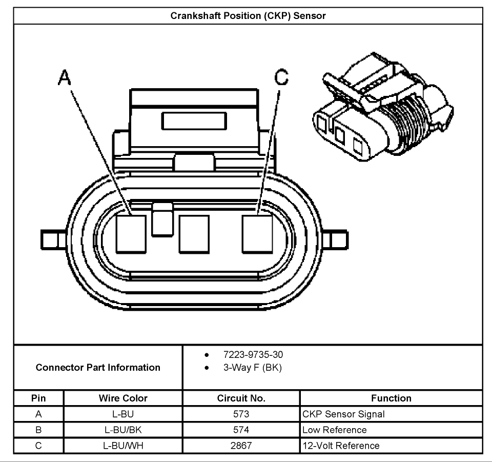
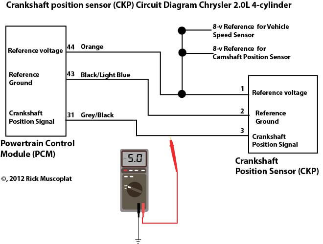
3 wire crank sensor wiring diagram the 3 wire crank sensor has three wires mentioned below. Reference voltage wire signal wire ground all of these wires are connected to the ecu. If it's replaced, you'll need to have the crankshaft position sensor relearn procedure done with a scan tool that is capable. If the key has been turned on while the connector was unplugged.

To properly read a cabling diagram, one offers to learn how the components within the program operate. For example , in case a module will be. The following tutorial will help you to test the camshaft position (cmp) sensor: 18 pics about crankshaft position sensors : | repair guides | electronic engine controls | crankshaft position, 2l chrysler crankshaft sensor wiring diagram. Crankshaft position sensor wiring harness diagram bmw e90 e91 e92 e93if you need to find the crankshaft position sensor wiring harness and the wire order for. On 2002 gmc sonoma 4. 3 crank sensor wiring diagram. 4. 3 crank sensor wiring diagram wiring car repair diagrams mitchell 1 diy. The following tutorial will help you to test the camshaft.

2002 Gmc Sonoma 4.3 Crank Sensor Wiring Diagram

2002 Gmc Sonoma 4.3 Crank Sensor Wiring Diagram
Image by wiringall.com

2002 Gmc Sonoma 4.3 Crank Sensor Wiring Diagram

2002 Gmc Sonoma 4.3 Crank Sensor Wiring Diagram
Image by wiringall.com

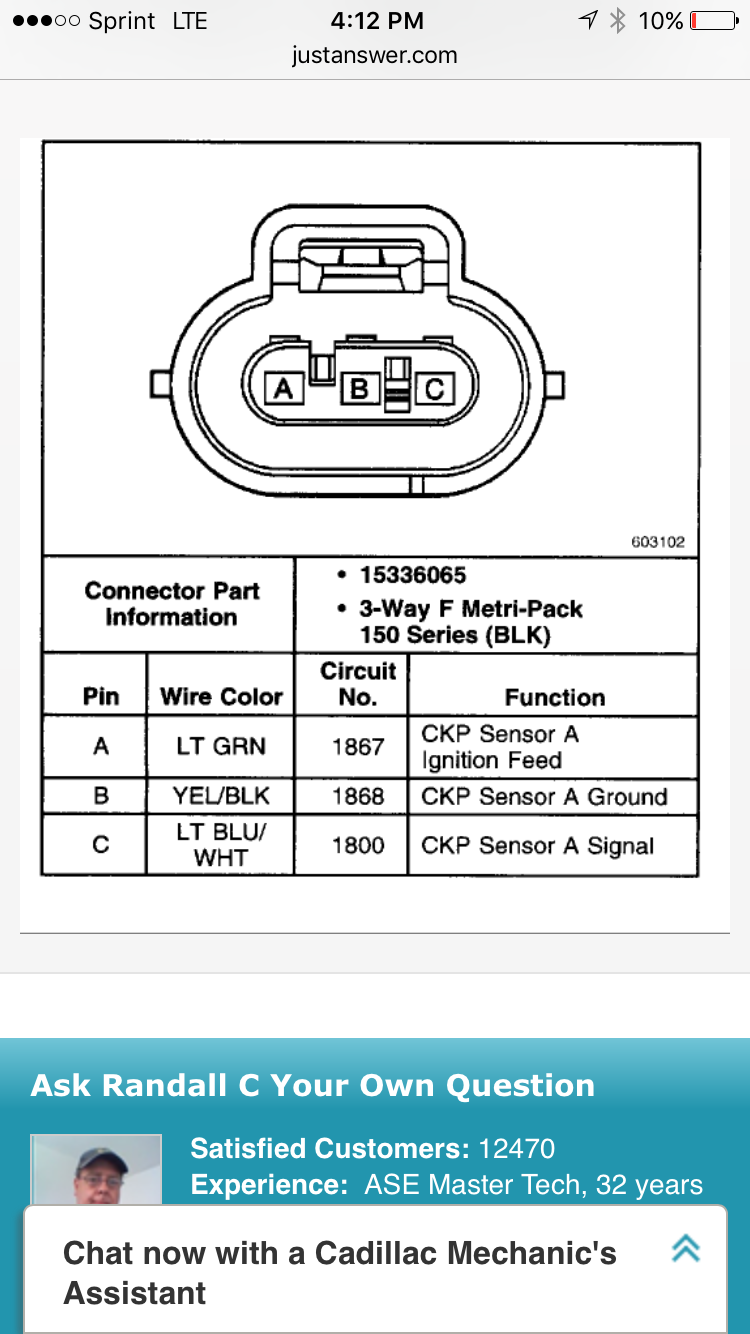
Wiring for upper crankshaft position sensor connector

Wiring for upper crankshaft position sensor connector
Image by www.justanswer.com

MS3 crank position sensor wiring - Miata Turbo Forum - Boost cars, acquire cats.

MS3 crank position sensor wiring - Miata Turbo Forum - Boost cars, acquire cats.
Image by www.miataturbo.net

Crankshaft Position Sensor Connector Wiring - Crank by Design

Crankshaft Position Sensor Connector Wiring - Crank by Design
Image by crankbydesign.blogspot.com

Crankshaft Sensor Wires: My Vehicle Has Three Wires for the

Crankshaft Sensor Wires: My Vehicle Has Three Wires for the
Image by www.2carpros.com

2L Chrysler crankshaft sensor wiring diagram — Ricks Free Auto Repair Advice Ricks Free Auto

2L Chrysler crankshaft sensor wiring diagram — Ricks Free Auto Repair Advice Ricks Free Auto
Image by ricksfreeautorepairadvice.com

Crankshaft position sensor connectors - GM Forum - Buick, Cadillac, Olds, GMC & Pontiac chat

Crankshaft position sensor connectors - GM Forum - Buick, Cadillac, Olds, GMC & Pontiac chat
Image by www.gmforum.com

Delphi Crankshaft And Camshaft Position Sensor Wiring Diagram

Delphi Crankshaft And Camshaft Position Sensor Wiring Diagram
Image by diagramweb.net

what color wires on crank position sensor?? - CorvetteForum - Chevrolet Corvette Forum Discussion

what color wires on crank position sensor?? - CorvetteForum - Chevrolet Corvette Forum Discussion
Image by www.corvetteforum.com

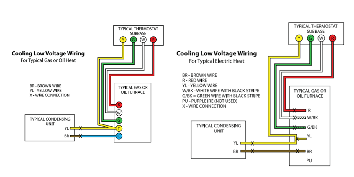
Low Voltage Wiring Diagrams

Low Voltage Wiring Diagrams

nest Hello Wiring Diagram, Nest Hello Advanced Wiring Diagram, 6.25 MB, 04:33, 63,749, gt8monster, 2018-06-16T10:14:46.000000Z, 19, Nest Hello Doorbell: 18 Questions/Answers You Need To Know - Smart Home Point, www.smarthomepoint.com, 1057 x 852, png, nest diagram hello doorbell wiring google camera chimes chime install multiple lh4 googleusercontent answers questions know need pre, 20, %ef%bb%bfnest-hello-wiring-diagram, Anime Arts

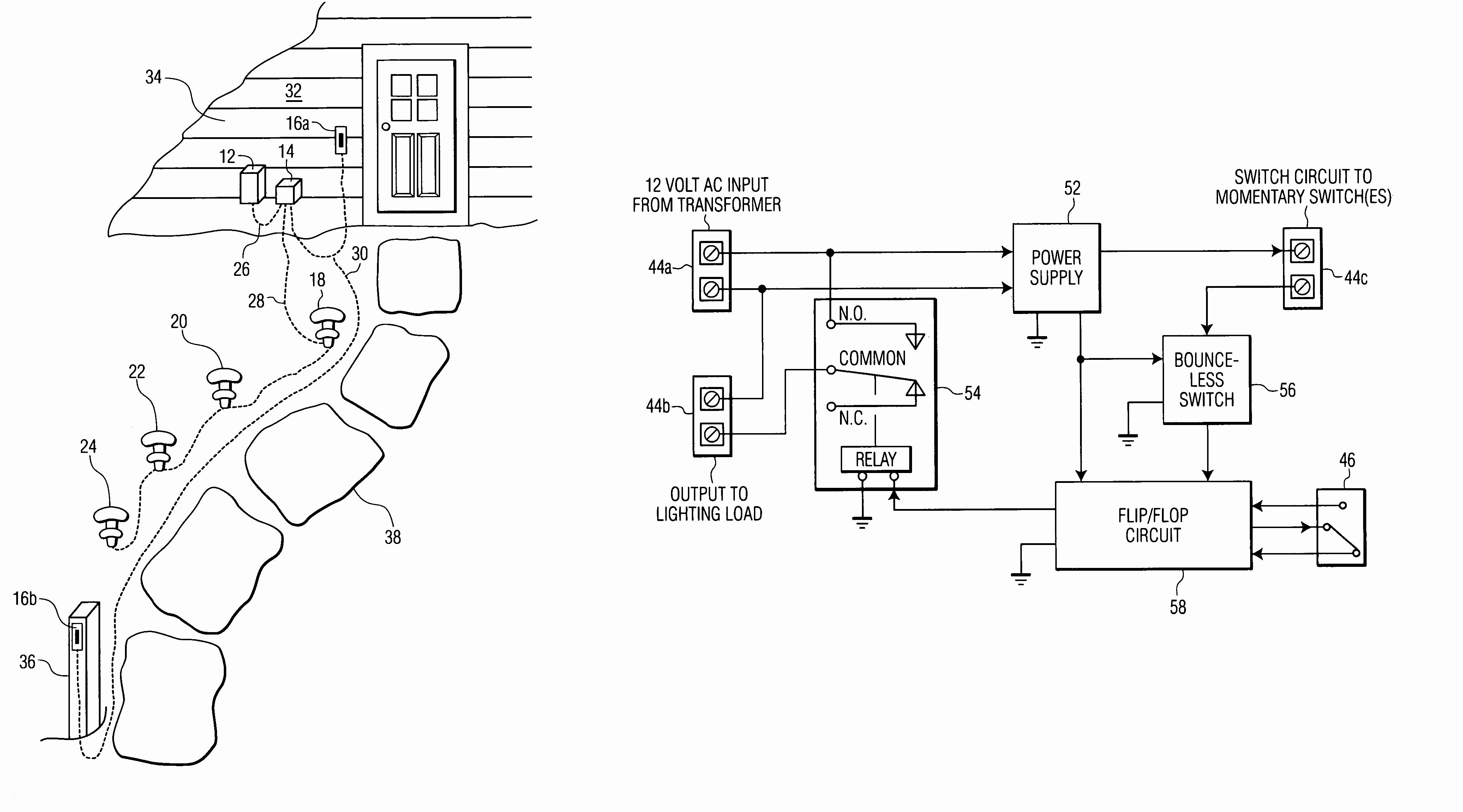
Later on, we'll get into specific use cases for low voltage wiring, but first, let's discuss why you would install low voltage wiring in a building. Read this article to learn more about what is low voltage cable Low voltage motor wiring diagram. To properly read a electrical wiring diagram, one offers to learn how the particular components in the system operate.

Heat pump low voltage wiring diagram effectively read a electrical wiring diagram, one provides to know how the particular components in the method operate. For instance , when a module is usually powered up and it sends out a new signal of fifty percent the voltage plus the technician will not know this, he'd think he offers an issue, as he or she would expect the 12v signal. Rheem heat pump low voltage wiring diagram. Rheem heat pump low voltage wiring diagram from www. gridgit. com. To properly read a electrical wiring diagram, one offers to learn how the particular components in the system operate. For instance , if a module is usually powered up and it sends out a new signal of half the voltage and the technician will not know. Low voltage lighting systems can carry a higher amount of current and will need larger diameter wires. In the left diagram below, a 20 watt (w) bulb with a 120v source draws. 16 amp. In the right diagram below, a 20 w bulb with a 12v source draws 1. 6 amps (10 times more current than a 120v source).

Low Voltage Transformer Wiring Diagram Download

Low Voltage Transformer Wiring Diagram Download
Image by wholefoodsonabudget.com

Image result for low voltage lighting diagram | Lighting diagram, Low voltage lighting, Relay

Image result for low voltage lighting diagram | Lighting diagram, Low voltage lighting, Relay
Image by www.pinterest.ca

8 Nice Low Voltage Light Switch Wiring Diagram Galleries - Tone Tastic

8 Nice Low Voltage Light Switch Wiring Diagram Galleries - Tone Tastic
Image by tonetastic.info

Low Voltage Outdoor Lighting Wiring Diagram - Deltagenerali - Low Voltage Landscape Lighting

Low Voltage Outdoor Lighting Wiring Diagram - Deltagenerali - Low Voltage Landscape Lighting
Image by 2020cadillac.com

Central Vac Low Voltage Wiring - Wiring Diagram

Central Vac Low Voltage Wiring - Wiring Diagram
Image by facybulka.me

Low Voltage Lighting Transformer Wiring Diagram - Cadician's Blog

Low Voltage Lighting Transformer Wiring Diagram - Cadician's Blog
Image by 2020cadillac.com

Hvac Low Voltage Wiring Furnace / Room thermostat wiring diagrams for HVAC systems / But if you

Hvac Low Voltage Wiring Furnace / Room thermostat wiring diagrams for HVAC systems / But if you
Image by fredbeattie34.blogspot.com

Trane 4ttb3024g1000aa Low Voltage Wiring Diagram

Trane 4ttb3024g1000aa Low Voltage Wiring Diagram
Image by wiringall.com

Three, Switch Wiring Voltage Popular Low Voltage Outdoor Lighting Wiring Diagram Beautiful

Three, Switch Wiring Voltage Popular Low Voltage Outdoor Lighting Wiring Diagram Beautiful
Image by tonetastic.info

Ac Low Voltage Wiring Diagram | Free Wiring Diagram

Ac Low Voltage Wiring Diagram | Free Wiring Diagram
Image by ricardolevinsmorales.com

Saturday, October 22, 2022

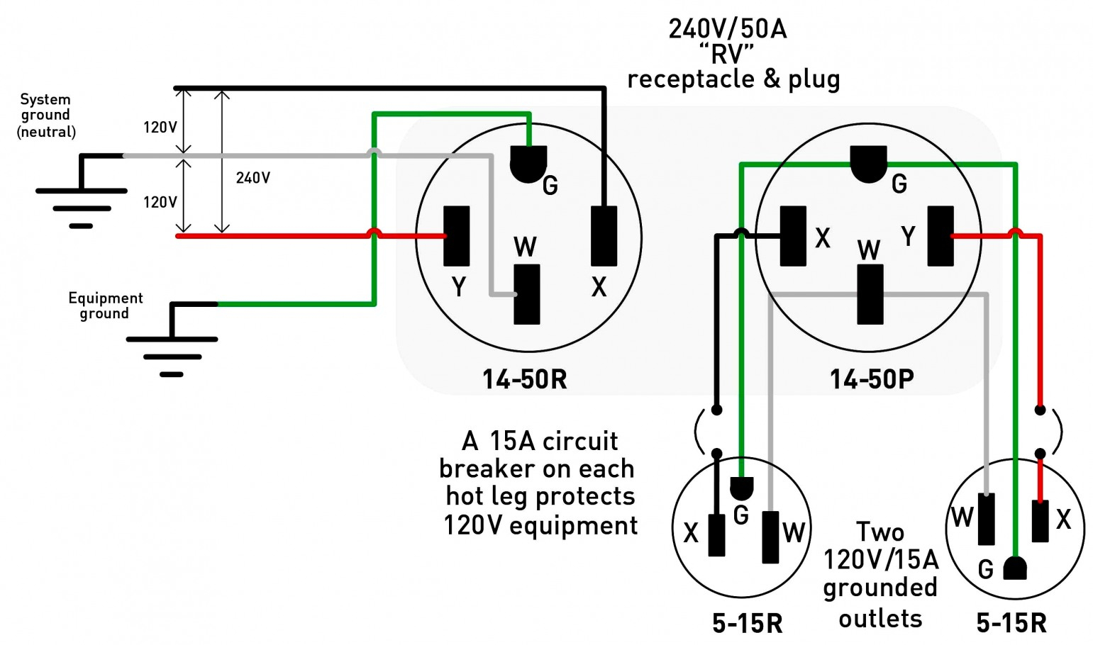
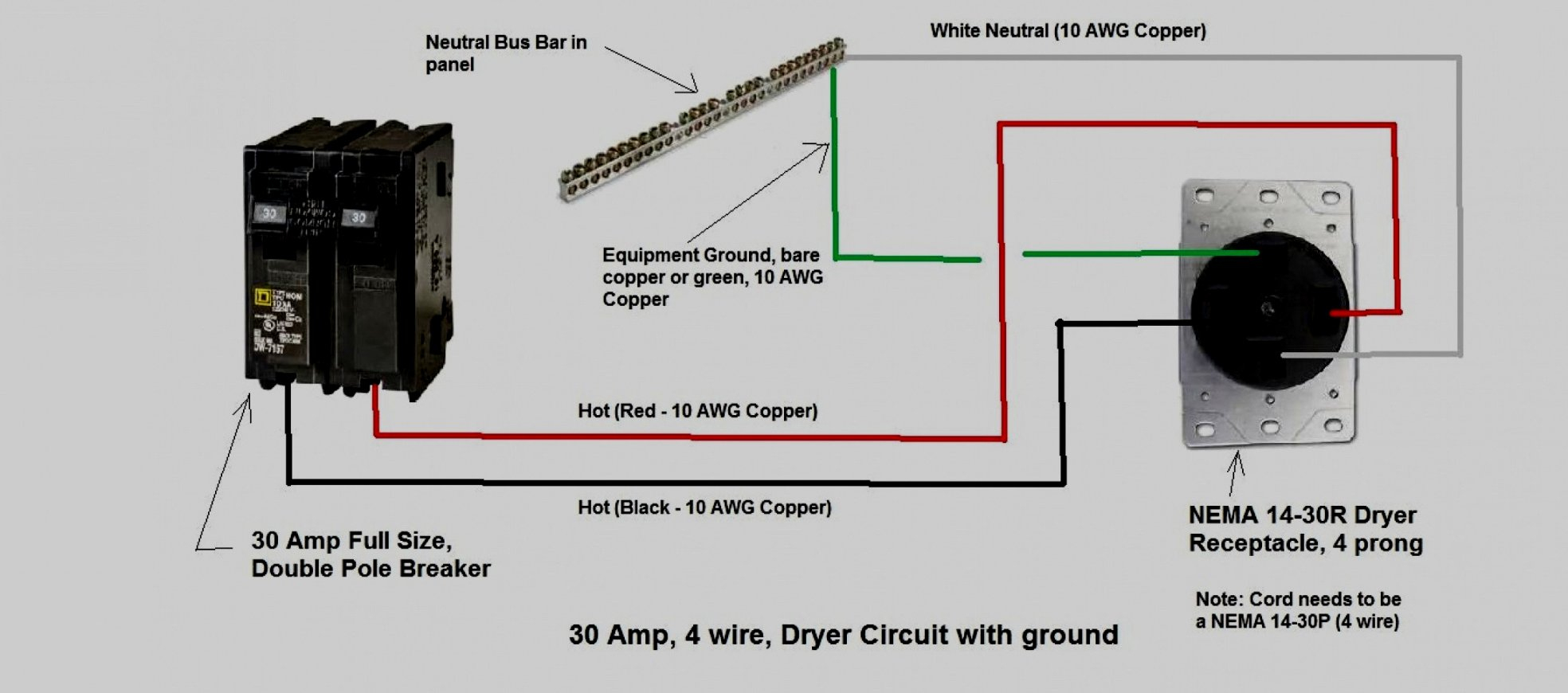
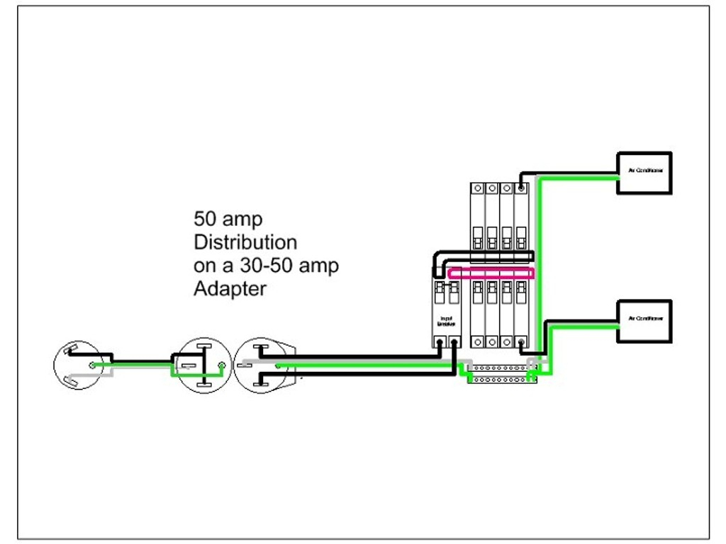
30 Amp Plug Wiring Diagram

30 Amp Plug Wiring Diagram

nest Hello Wiring Diagram, Nest Hello Advanced Wiring Diagram, 6.25 MB, 04:33, 63,749, gt8monster, 2018-06-16T10:14:46.000000Z, 19, Nest Hello Doorbell: 18 Questions/Answers You Need To Know - Smart Home Point, www.smarthomepoint.com, 1057 x 852, png, nest diagram hello doorbell wiring google camera chimes chime install multiple lh4 googleusercontent answers questions know need pre, 20, %ef%bb%bfnest-hello-wiring-diagram, Anime Arts

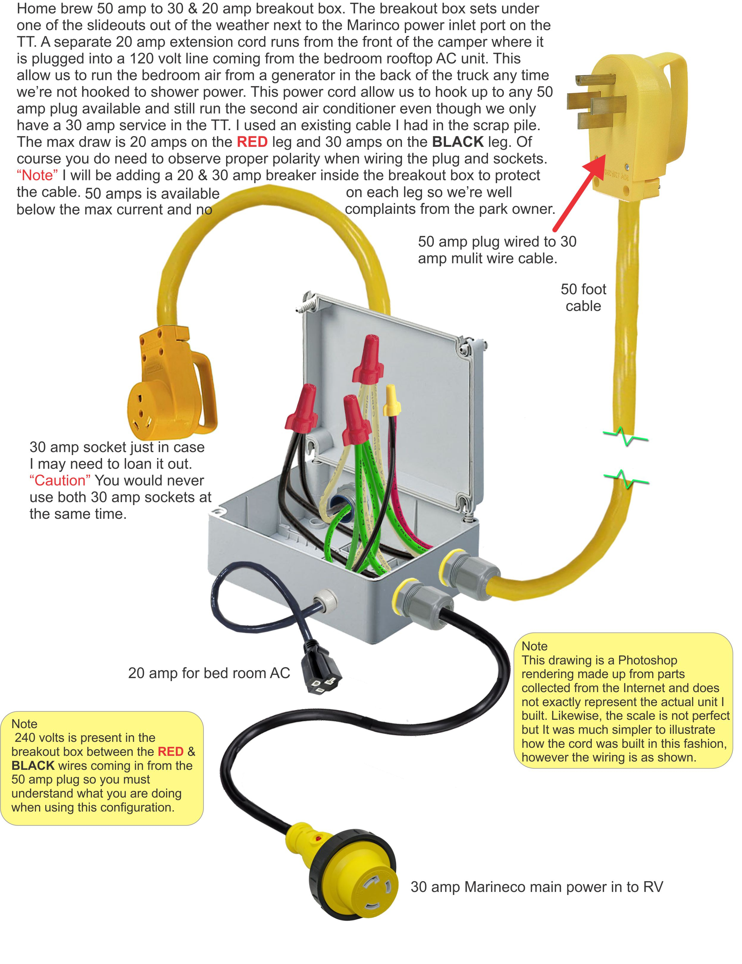
Rv net open roads forum running 2 ac units on 30 amp. L14 30p to cs6364c power cable plug adapter 30a 250v 1 foot 8 4 soow wire. Zc5hao 30 amp nema l5 30p generator power inlet box for 3 g cord 125 volt 3750 watts weatherproof anty rust outdoor use etl listed canada. Parkworld 885217 power adapter cord generator 4 g 30 amp twist lock.

Mount and wire the outlet box · step 3: Shut off the main power · step 4: Install the 30a branch circuit breaker. Follow the color codes, which match wires to connections. Wiring diagram for 30 amp plug source: Read electrical wiring diagrams from unfavorable to positive and redraw the signal being a straight collection. All circuits are usually the same : Voltage, ground, individual component, and switches. Wiring diagram for 30 amp plug source:

30 Amp Twist Lock Plug Wiring Diagram | Cadician's Blog

30 Amp Twist Lock Plug Wiring Diagram | Cadician's Blog
Image by 2020cadillac.com

30 Amp Rv Plug Wiring Diagram | Fuse Box And Wiring Diagram

30 Amp Rv Plug Wiring Diagram | Fuse Box And Wiring Diagram
Image by stickerdeals.net

Collection Of 30a 250v Plug Wiring Diagram Sample

Collection Of 30a 250v Plug Wiring Diagram Sample
Image by worldvisionsummerfest.com

30 Amp Plug Wiring Diagram | Wiring Diagram

30 Amp Plug Wiring Diagram | Wiring Diagram
Image by annawiringdiagram.com

30 Amp Rv Plug Wiring Diagram - Collection - Wiring Diagram Sample

30 Amp Rv Plug Wiring Diagram - Collection - Wiring Diagram Sample
Image by faceitsalon.com

30 Amp Plug Wiring Diagram | Wiring Diagram

30 Amp Plug Wiring Diagram | Wiring Diagram
Image by annawiringdiagram.com

30 Amp Generator Plug Wiring Diagram - Rv Electricity The Abcs Of Campground Power And Grounding

30 Amp Generator Plug Wiring Diagram - Rv Electricity The Abcs Of Campground Power And Grounding
Image by jhonshonmnn.blogspot.com

30 Amp Plug Wiring Diagram | Wiring Diagram

30 Amp Plug Wiring Diagram | Wiring Diagram
Image by annawiringdiagram.com

30 Amp Generator Plug Wiring Diagram | Wiring Diagram

30 Amp Generator Plug Wiring Diagram | Wiring Diagram
Image by 2020cadillac.com

30 Amp Rv Plug Wiring Diagram | Fuse Box And Wiring Diagram

30 Amp Rv Plug Wiring Diagram | Fuse Box And Wiring Diagram
Image by stickerdeals.net