Yamaha Xs850 Wiring Diagram

Rj11 Socket Wiring Diagram Australia, How to punch down an RJ11 Telephone Jack, 6.36 MB, 04:38, 387,634, CableSupply.com, 2009-08-05T00:16:...

Monday, September 5, 2022

07 Zx6r Tail Light Wiring Diagram

1990 mitsubishi eclipse gst radio wiring diagram. Help with tail light wiring harness.


Zx6r Tail Light Elegant Wiring Diagram Image

Without this critical feedback, the ecu will not provide ignition spark to the coils and spark plugs.
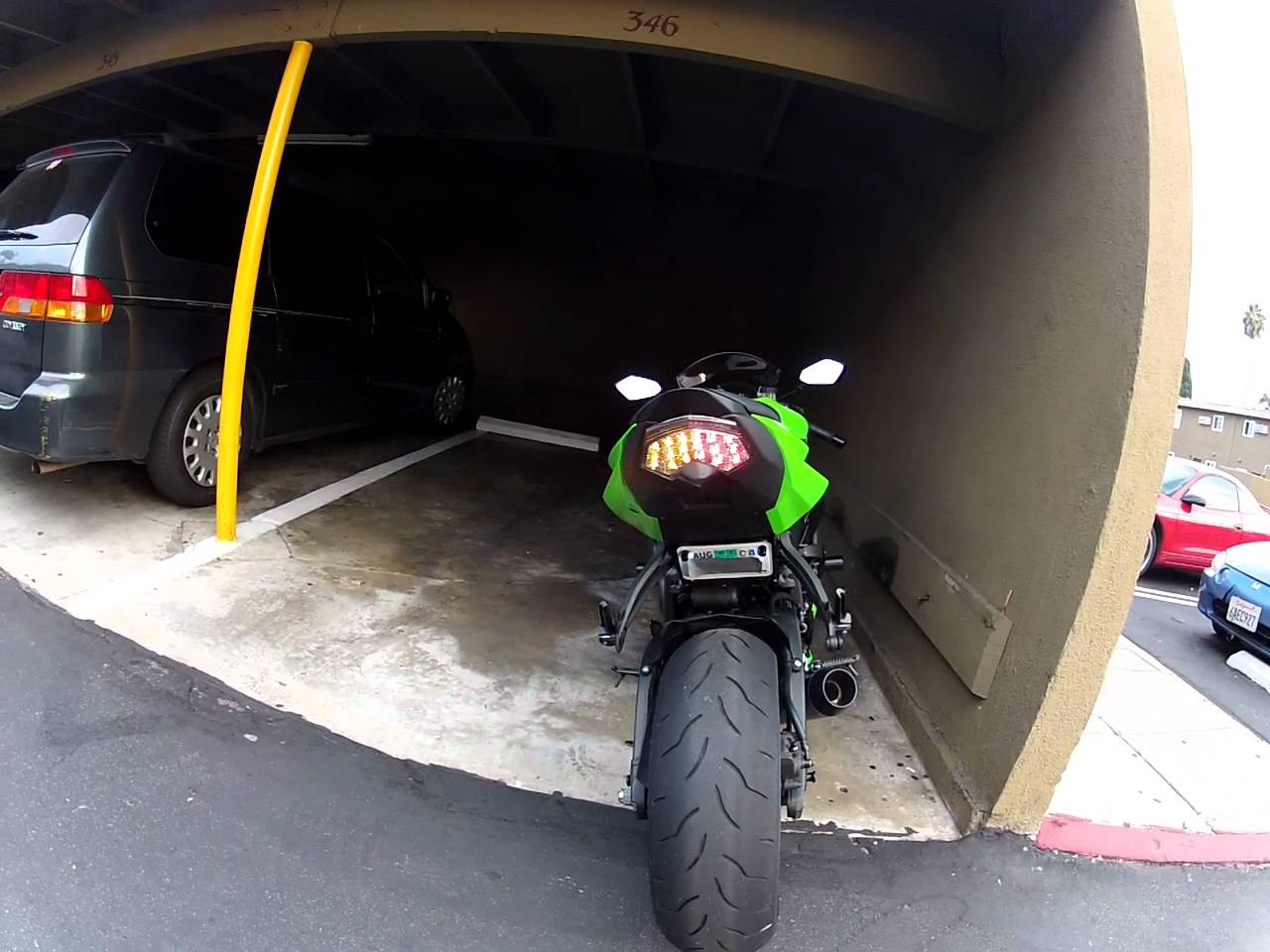
07 zx6r tail light wiring diagram. I just bought a tail light with integrated turn signals for my zzr600. Discussion starter · #1 · jun 30, 2013. How to install integrated tail light.

In the same way as trying to remove, replace or fix the wiring in an automobile, having an accurate and detailed integrated tail light wiring. Na 1.0 (my version of the diagram) **if you have any requests or suggestions, please leave a comment here and i will look into. They undergo comprehensive evaluation to ensure the hightest quality and durability standards to help maximize the life of your vehicle, and give you peace of mind that your kawasaki is always operiating at peak performance.

I have made this diagram easy to follow and added some detail. The first stage is to strip and tin the 3 wires (red, black, green) from the integrated led light unit. Posted on dec 27, 2009

Discussion starter · #1 · dec 31, 2011. Perhaps i'm reading it wrong but here goes,. The wiring to the tail light needs to be checked its grounding somewhere.

High performance, premium, designed to be used with synthetic or conventional oils: Diagram cbr600rr wiring enthusiast forums for honda cbr cbr600 08 03 600rr help i d electrical connector motorcycle 2003 2006 07 wire forum 2004 harness parts stop light radiator oem cbr600f 87 90 in under front. Installing integrated tail light but the wiring diagram is off.

The sensor is located on the right side of Garmin gps 128 wiring diagram. Ships from and sold by diamondsproducts.

So i got ticketed for not having a running break light and the wires are all fukked up so i need some help. Motorcycle tail light, sportbike tail light | nicecycle.com the wiring harness for the brake lights matches up perfectly and i got that installed and working. Joined dec 25, 2011 · 629 posts.

Kawasaki er650 er6n er 650 electrical. Kawasaki zx6 integrated tail light/fender eliminator zx6r. Trace it from the rear to front.

Kawasaki er250 er 250 electrical wiring harness diagram schematic here. The process also needs to be repeated for the stock wires. Discussion starter · #1 · jan 11, 2010.

Check under the seat there is a yellow wire coming out of the ecu that is touhed to chasis ground in order to retreve the trouble codes, the wire may be pinched and contacting ground, causing the light to flash codes. 05 cbr600rr wiring diagram.clicking this will make more experts see the question and we will remind you when it gets answered. 1 of 2 go to page.

There are two other wires out of the new tail light (see second attached picture) that obviously control the blinkers. Adr wiring diagram for aussies crf450x thumpertalk. Use our comprehensive oem schematic diagrams to find the exact parts you need to get the job done, and get riding!

Kawasaki genuine parts are the only parts on the market specifically engineered and tested to fit your kawasaki vehicle. Joined mar 20, 2009 · 116 posts. Posted on sep 19, 2009.


Wiring Diagram Zx6r 07 Home Wiring Diagram


Zx6r Tail Light Elegant Wiring Diagram Image


Wiring Diagram Zx6r 07 Home Wiring Diagram


Zx6r Tail Light Elegant Wiring Diagram Image


Tail Light with integrated Turn Signals for For Kawasaki Ninja ZX6R 636 Z750S 0506 ZX10R 0607


Wiring Diagram Zx6r 07 Home Wiring Diagram
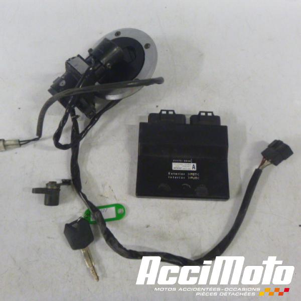

2006 Kawasaki Zx6r Wiring 88 Wiring Diagram


20072008 Kawasaki ZX6R LightWorks ChromeCoated Tail Light with Integrated Signals 2007 2008


Wiring Diagram Zx6r 07 Home Wiring Diagram


2006 Kawasaki Zx6r Wiring


Zx6r Tail Light Elegant Wiring Diagram Image


DMP LED Integrated tail light wiring question ZX6R Forum


Guide Integrated LED tail light upgrade ZX6R Forum


Zx6r Tail Light Elegant Wiring Diagram Image


B11 2007 Kawasaki Ninja Zx6r Wiring Diagram Wiring Library


HELP!need 05 636 wiring diagram info ZX Forums


Is it possible to install this integrated tail light on my 07? Pictures of the wires ZX6R Forum


Is it possible to install this integrated tail light on my 07? Pictures of the wires Kawasaki


DMP LED Integrated tail light wiring question ZX6R Forum

Sunday, September 4, 2022

Allis Chalmers Wd Wiring Diagram

International tractor wiring harness in 2021 alternator tractors ford tractors pin on heavy equipment parts and attachments business and industrial a wiring diagram is a simplified standard photographic. I bought a 1950 wd.


[DIAGRAM] 7060 Allis Chalmers Wiring Diagrams FULL Version

Please use the navigational links on your left to explore our website.

Allis chalmers wd wiring diagram. Wellborn collection of allis chalmers wd wiring schematic diagram. It reveals the components of the circuit as streamlined shapes, and the power and also signal links between the gadgets. It has a regulator, and does not have the cut out box or custom light switch anymore.

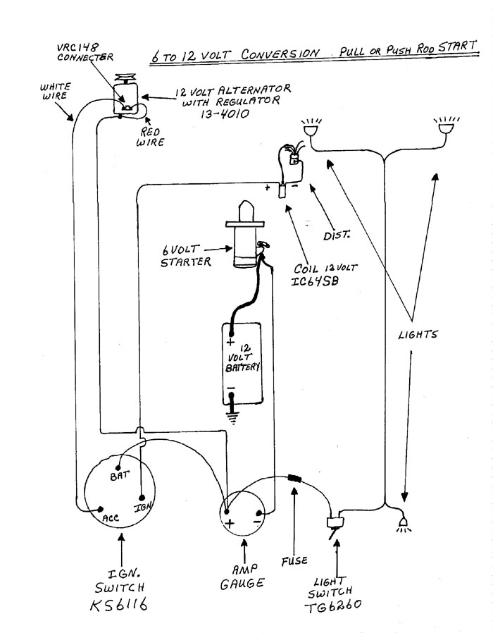
For example , when a module will be powered up and it also sends out a new signal of 50 percent the voltage and the technician does not know this, he'd think he provides a problem, as he would expect a 12v signal. 6 to 12 volt conversion the ign. Switch is key type with acc.

Wd wd45 with distributor 12 volt conversion coil napa echlin ic64sb 12 volt with an internal resistor. Allis chalmers wd ignition wiring thank you for visiting our site, this is images about allis chalmers wd ignition wiring posted by maria rodriquez in allis category on. Allis chalmers wd 12 volt wiring diagram.

I am looking for a d17 wiring diagram gas engine 12 volt with alternator local guy has one that he is having trouble with so i am trying to help him out. Pin on heavy equipment parts and attachments business and industrial a wiring diagram is a simplified standard photographic representation of an electric circuit. Wiring diagram is a technique of describing the configuration of electrical equipment installation, eg electrical installation equipment in the substation on cb, from panel to box cb that covers telecontrol & telesignaling aspect, telemetering, all aspects that require wiring diagram, used to locate interference, new auxillary, etc.allis chalmers wd wiring diagram.

Wd 45 wiring diagram discussion in the allis chalmers forum at yesterday's tractors. Wd wd45 with distributor 12 volt conversion coil napa echlin ic64sb 12 volt with an internal resistor. It is 6 volt positive ground.

To separate the alternator wire from the dist wire. Effectively read a wiring diagram, one provides to know how the components inside the method operate. Allic chalmers wd electrical wiring diagram charlie fenner friday, november 18, 2011 (0).

October 27, 2018 by larry a. Allis chalmer wd wiring diagram found in: Wiring harness kit (for tractors with 1 wire alternator), service manual:

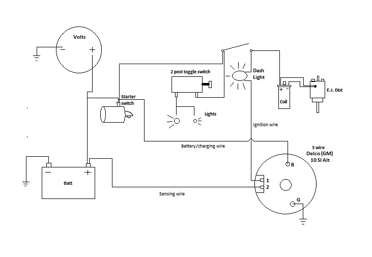
The electrical system is modified a little. Allis chalmers wd 12 volt wiring diagram. So do you all know of any wiring diagram so i can check to see if it is wired or diagram of how the wiring should be for a wd allis with a 6 volt.

Allis chalmers d17 electrical system parts for sale at discount prices. Allis chalmers wd wiring schematic diagram collections of ac wd wiring diagram best allis chalmers b wiring diagram b2network. Allic chalmers wd electrical wiring diagram stu (on) monday, may 26, 2008 (0)

Allis chalmers wd wiring diagram. A wiring diagram is a simplified standard photographic representation of an electric circuit. Allic chalmers wd electrical wiring diagram glenn sunday, february 08, 2009 (1).

Allis chalmers wiring diagram six volt coil dist by a l. Wd wiring diagram discussion in the allis chalmers forum at yesterday's tractors.


[DIAGRAM] Allis Chalmers Wd Starter Wiring Diagram FULL


wiring diagram WD 45 Allis Chalmers Forum Yesterday's


Alli Chalmer Wd 12 Volt Wiring Diagram Wiring Diagram


wd 45 6 volt wiring diagram AllisChalmers Forum


Allis Chalmers D15 Wiring Diagram Wiring Diagram Database


611 Allis Chalmers Wiring Schematic schematic and wiring


Allis Chalmers Wd Wiring Diagram


Allis Chalmers Wd 6 Volt Wiring Diagram


Wiring Diagram Database Allis Chalmers Wd Parts Diagram


[DIAGRAM] Allis Chalmers Wd Starter Wiring Diagram FULL


6 Volt Generator Wiring Diagram Fuse Box And Wiring Diagram


wiring diagram generator AllisChalmers Forum


Alli Chalmer Wd Electrical Wiring Diagram Wiring Diagram


Allis Chalmers Wd Wiring Schematic Diagram schematic and


28 Allis Chalmers Wd Parts Diagram Wiring Diagram List


WD45 Voltmeter Wiring AllisChalmers Forum


Allis Chalmers 190 Diesel Alt Wiring Diagram


Allis Chalmers D 19 Wiring Diagram Wiring Forums


611 Allis Chalmers Wiring Schematic schematic and wiring

Saturday, September 3, 2022

Lowrance 3d Module Wiring Diagram

Bassin'we will be installing a nmea network between 2 lowrance hds units and also install a point 1. Airmar wiring diagram garmin b744 8 pin d s t blue.


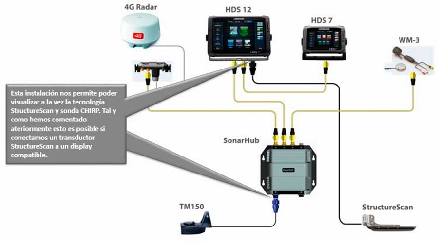
Lowrance SonarHub Chirp Module Simrad SonarHub Sounder Module

February 21, 2010 at 2:32 pm #1306574.

Lowrance 3d module wiring diagram. • there are 3 networks in the hds system: This differs from a schematic diagram where the plan of the elements interconnections on the representation generally does not correspond to the parts physical places in the completed gadget. 3 amp fuse red wire black wire 12 volt battery to speed/ temp sensor to gps module to nmea interface to p connector on accura.

Websites under the structurescan 3d transducer documentation section. Lowrance hds 7 wiring diagram. Hereby, navico holding as declares that this hds is in compliance.

70778c 159 69 3 193 evh wiring diagram wiring resources. Installation instructions for installing the lowrance structurescan hd processor module unit for a more panoramic view underwater. The positive supply wire (red) should always be connected to (+) dc with a fuse or a circuit breaker (closest available to fuse rating).

The blue wire should not be used.! Lowrance hds 16 carbon with structurescan 3d module and transducer. Installing the new lowrance structurescan hd module.

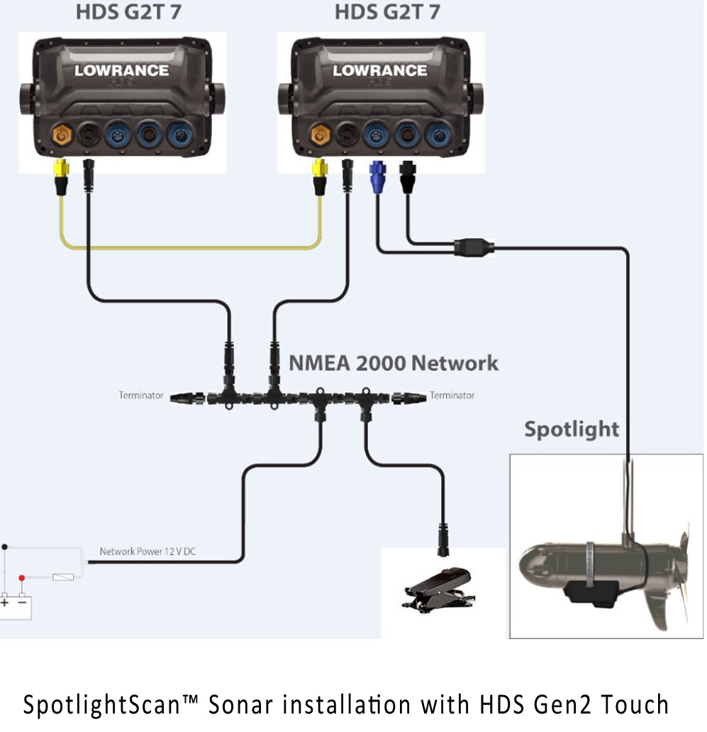
Before attempting to rewire a transducer connector you should: Senin, 13 desember 2021 reviewed in the united states on july 28, 2017. Below are a couple diagrams of a lowrance nmea 2000 network.

Lowrance nmea cable wiring diagram fusion 700 marine stereo. Check to see if an adapter cable exists (see the adapters page). When wiring the hds follow the guidelines below.

In this video i explain how to wire up a lowrance gps sonar combo unit. Power controlled by external switch the unit will turn on/off when power is applied/removed. The structurescan 3d module from lowrance.

I found the diagrams online and modified them to help you during. Transducer shield & saver products are sold by many authorized retailers across the united states and canada. 29+ lowrance point 1 wiring diagram.

Connect the yellow wire to the red wire via a switch after the fuse. See our full range of transducers and the latest marine electronics. Cable wiring diagram in your hds installation manual for more information.

Below are a couple diagrams of a lowrance nmea network. These diagrams are for the use of professional installers. I found the diagrams online and modified them to help you during installation.

4 50 khz transducer 192 khz Washer and plastic bracket) attach it to the transducer as shown in the diagram above. This manual is a reference guide for installing the lowrance.

Ido » community » forums » fishing forums » toys for big boys » lowrance electronics » wiring diagram for lss1. I found the diagrams online and modified them to help you during. Cutting a hole in a panel, make sure that there are no hidden electrical wires or other 1:

Use this diagram to connect the lvr to a lowrance gps unit that is not connected to a radar unit. 23.12.2018 · lowrance help topics networking diagrams wiring interfacing to hds gen2 3 sonar server german 7 gen 1 manual nema0183 interface. Mike gofron shows the installation of a lowrance hds10 and hds8 with structure scan.

This power cable diagram does not apply to hds units it is meant for the lcx/lms units please see your manual for proper nmea2000 powering. About lowrance 7 hds wiring diagram. These include wiring of the power cable and a typical red network bus.

I turn to page 26, and see the diagram showing the wiring fan out that identifies the. Lowrance sonarhub chirp module simrad sonarhub sounder module. The following diagram demonstrates a typical small nmea network:

7fb wiring diagram for lowrance structure scan epanel


Lowrance HDS7 Gen3 TM/Transducer 83/200 Structurescan 3D


Lowrance StructureScan HD LSS2 Australia DownScanning


Lowrance StructureScan HD Skimmer Transom Mount Transducer


Lowrance LSS2 StructureScan HD Sonar System


layout for NMEA network The Hull Truth Boating and


Simrad SonarHub with transom StructureScan Hd transducer


Lowrance 00012916001 HDS12 Gen3 w/ Transducer


Sonar


Buy Lowrance HDS7 Gen 2 Fishfinder and GPS Chartplotter


Lowrance, Simrad StructureScan 3D Module and Transom mount


Lowrance 00012914001 HDS7 Gen3 w/ Transducer TackleDirect


StructureScan 3D


3D Structure Scan Installation What's in the box? Simrad


Lowrance LSS1 StructureScan Sonar System


Lowrance SONAR


Lowrance Lowrance HDS9 Gen3 with 83/200 Transom Mount


Lowrance StructureScan HD LSS2 Australia DownScanning


Index of /images/Open_Source_Towed_Sonar_ROV


11 best Installing and mounting Lowrance HDS7, HDS9 and