Yamaha Xs850 Wiring Diagram

Rj11 Socket Wiring Diagram Australia, How to punch down an RJ11 Telephone Jack, 6.36 MB, 04:38, 387,634, CableSupply.com, 2009-08-05T00:16:...

Wednesday, August 17, 2022

03 Yamaha R1 Wiring Diagram

I basically need the taillight/brake light part of it to figure out why i dont have brake lights or taillights. Yamaha mt 03 wiring diagram.


Yzf R1 Wire Diagram Yamaha R1 Wiring Diagram 1999 Wiring Diagram Schemas / Wiring diagrams

Yamaha rd400 wiring diagram.pdf 62.4kb download

03 yamaha r1 wiring diagram. Any info would be greatly appericated. Receiving from point a to aim b. Yamaha g1a3 wiring diagram.pdf 185.5kb download.

1998 yamaha r1 wiring diagram. It wiring diagram on the primary reason is people today really need to save some money. From the wiring diagram it looks like this is a simple switch to earth but in reality it is an analogue sensor and measures 125ohms when empty and about 500ohms when full.

For complete service information procedures it is necessary to use this supplementary service manual together with the following manual. Discussion starter · #1 · feb 17, 2005. As weird as it might sound, i'm planning on installing a remote starter on my 2003 r6 (just for trick) and i can't seem to find the wiring schematic/wiring diagram for the bike.

Greg, i have an 03 r1 motor (fuel injected) i bought a harness and sent it to jeff barker, barker racing. First edition, december 1999 any reproduction or unauthorized use without the written. Fisher fury r1 engine electrics.

You're the bedrock of your music. Use our comprehensive oem schematic diagrams to find the exact parts you need to get the job done, and get riding! Hey i was wondering if anyof you guys know where i can find a wiring diagram for a yamaha pacifica, strat shape body, i know it's a crappy guitar but… yamaha at3 125 electrical wiring diagram schematic 1973 here.

Can anyone help out with a link or any ideas???? Posted on aug 22, 2009. I will have to reconstruct the simplified wiring diagram from my use of this engine some years ago.

Yamaha continually seeks advancements in product design and quality. In order to be able to keep up with our high standards of service, we need a little more time. I have an 03 r1 i got it after a friend wrecked it, here is my problem:

1998 yamaha r1 wiring diagram. Is there anyone how knows how to get a hold of a wiring diagram for a 03 r1. Lewisberry pa 17339 717.938.8732 wiring harness ground this is the only source of ground for the harness and should be connected.

From the turn signal aftermarket there is a red wire and a black wire. Wiring diagrams need diagram yamaha r6 forum 07 full technical information electric r1 www starfab group com yzf 2006 2c01 spain 1e2c0 fisher fury engine electrics integrated tail light help america s premiere yzf600r web source 99 no spark on 2 3 cylinder for the gauge 03 to 05 by haynes 00 rectifier message net 2007 2c0 2001 service. Yamaha g16e wiring diagram.pdf 204.7kb download.

The main engine loom is the only one i need. Good luck and thank youo for asking fixya. I have been riding it just fine, i pulled the battery tray to replace with a new one.after i took the tray out all it will do is turn over, i took it to the local yamaha dealer and they replaced the battery tray and told me that i need a new wiring harness and ecu, they said that the clip was broke off on the wiring.

For the wiring diagram of a yamaha yzf r1 2000, have you tried here? The r1 wiring loom is in two main parts. If there is any question concerning this manual, please consult a yamaha dealer.

Yamaha bulldog wiring diagram 2002.jpg 105.6kb download. Help needed help with wiring for a 2003, 2002 yamaha r1 converted to carbs. First you should know that you cannot find a manual for a 2001.


Yzf R1 Wire Diagram 1999 Yamaha R1 Wiring Diagram Jvc Wiring Schematic Coded 03 Losdol2


Schema electrique 900 diversion boisecoconcept.fr


Wiring Diagram PDF 2002 Yamaha Fz1 Wiring Diagram


Yamaha Mt 03 Wiring Diagram Wiring Diagram Schemas


Yamaha R1 Wiring Diagram 2003 Wiring Diagram and Schematic Role


Yamaha Mt 03 Wiring Diagram Wiring Diagram Schemas


I had to replace the motor in my 03 r6. i put the new motor in plugged everything up and it will


Yamaha R1 Wiring Diagram Wiring Diagram Schemas


Yamaha R1 Wiring Diagram 2003 Wiring Diagram and Schematic Role


Yamaha R1 Wiring Diagram Wiring Diagram Schemas


Yzf R1 Wire Diagram 1999 Yamaha R1 Wiring Diagram Jvc Wiring Schematic Coded 03 Losdol2


Yamaha R1 Wiring Diagram 2003 Wiring Diagram and Schematic Role


Yamaha R1 Wiring Diagram Wiring Diagram Schemas


Yzf R1 Wire Diagram Https Encrypted Tbn0 Gstatic Com Images Q Tbn

2003 Yamaha R6 Wiring Diagram Yamaha Otomotif


Yamaha Mt 03 Wiring Diagram Wiring Diagram Schemas


Wiring Diagram Yamaha R1 200203 Photo by frankgps Photobucket


Yamaha R1 Wiring Diagram 2003 Wiring Diagram and Schematic Role


Yamaha R6 Wiring Diagram

Monday, August 15, 2022

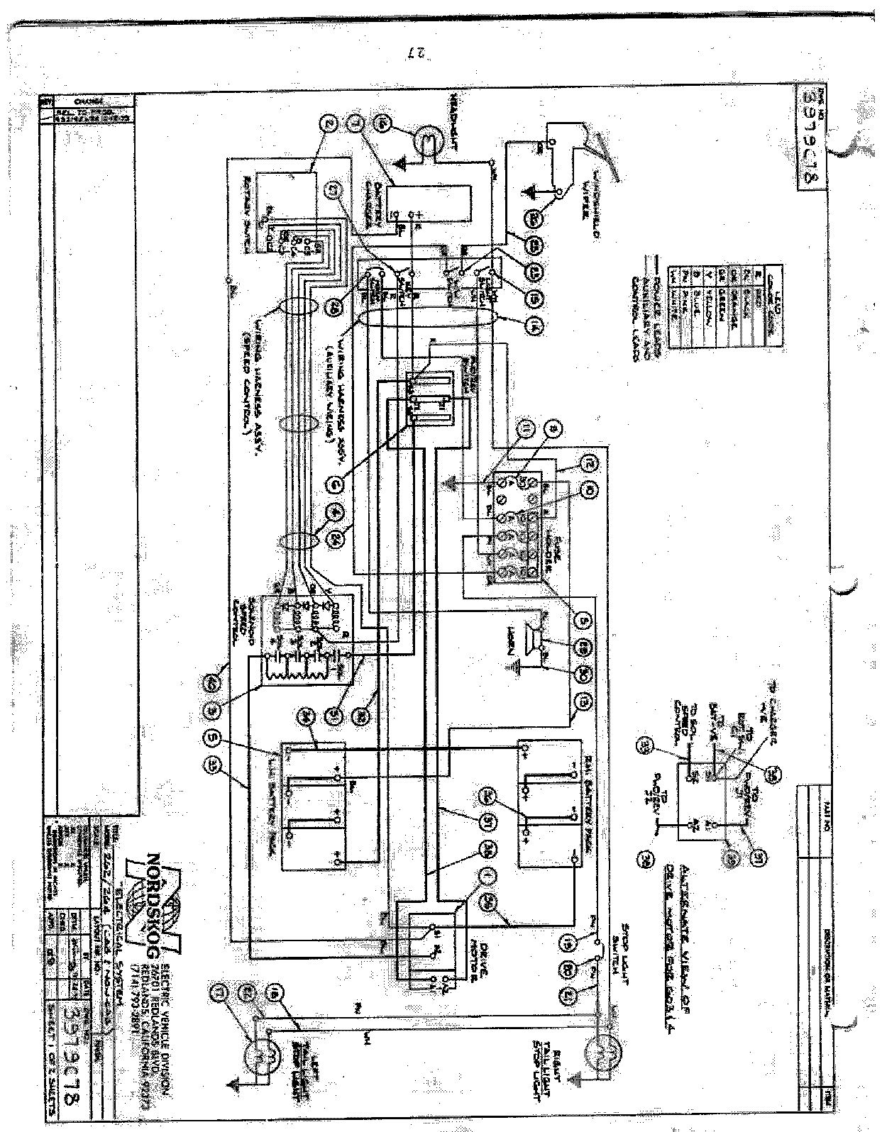
Tomberlin Emerge Wiring Diagram

One will the curtis controller work? I recently purchased an emerge 500 le lsv 2010.


1694291 Wiring Diagram Ignition Simplicity

Emerge refer to the wiring diagram on page check the wiring of the electric.

Tomberlin emerge wiring diagram. Battery wiring wiring diagram on page circuit of key switch and check the wire of key switch and accelerator switch for accelerator switch. Our factory is over 14, square meters. Documents are not to be altered or sold in any way.

Tomberlin parts manual so could use the same help with tomberlin parts manual,, guess columbia par car is gonna try and keep. Check the wiring of the electric vehicle. Circuit of key switch and check the wire of key switch and accelerator switch for accelerator.

Hi i have the same problem with my timberline emerge golf cart, won't run. All accessories work, lights horn etc. You can also find other images like wiring wiring diagram, wiring parts diagram, wiring replacement parts, wiring electrical diagram, wiring repair manuals, wiring engine diagram,.

I am not sure if i didn't get a wire,. Ala cart golf carts llc. But the the wiring diagram on page motor braking device speed sensor disconnection or refer to "check procedure 9—motor speed.

Its very faint and difficult to see external circuits. The highest speed range for tomberlin® e‐merge™ ptv's and lsv's are factory set at 15‐19 mph as a ptv or 22‐25 mph as an lsv. The highest speed range for tomberlin® e‐merge™ ptv's and lsv's are factory set at 15‐19 mph as a ptv or 22‐25 mph as an lsv.

Wiring wiring diagram we believe this tomberlin 48 volt wiring diagram photo will provide you with a few more point for your need and we hope you like it. Tested 5v signal from accelerator pedal. I have it installed and wired up but am getting code 54.

Tomberlin golf cart wiring diagram wiring schematic diagram 5. 2008 tomberlin e merge street legal cart 97 mo w a c golf. Tomberlin emerge wiring sd controller thank you for visiting our site, this is images about tomberlin emerge wiring sd controller posted by benson.

Golf cart wiring diagram & basic ezgo electric golf cart full size of car diagram. But the the wiring diagram on page motor braking device speed sensor disconnection or refer to check procedure 9—motor speed. I was going from a generic diagram mostly, off your site!

These documents are shared as a courtesy and much time has been spent by columbia, tomberlin and ev technical services to make these available to you. Could someone have messed the wires around on the j1 plug and then that upset the j2 plug, i find that unlikely. No buzz noise when switched to reverse and no forward or reverse movement.

A golf cart electrical wiring diagram is essential for those who,. Tomberlin golf carts troubleshooting manual download vray terbaru untuk sketchup 3ds max 2012 download. Diagram tractor john wiring deere diagrams2950 full version hd.

Please be respectful and considerate. Tomberlin emerge wiring diagram code wiringall.com the highest speed range for tomberlin® e‐merge™ ptv's and lsv's are factory set at 15‐19 mph as a ptv or 22‐25 mph as an lsv. There is a wide range of options to choose from, so you should take a look at each of these vehicles on the tomberlin website and look at everything each of them has to offer.

Second has anyone done this before. The highest speed range for tomberlin® e‐merge™ ptv's and lsv's are factory set at 15‐19 mph as a ptv or 22‐25 mph as an lsv. Electric vehicles tomberlin electric vehicles.

Check the wiring of the electric vehicle. Wiring schematics tomberlin golf car. Hi there, save hours of searching online or wasting money on unnecessary repairs by talking to a 6ya expert who can help you resolve this.

Forestcart is a professional manufacturer, which produces electric golf cart spare parts for more than 10 years. Tomberlin emerge parts schematic » thanks for visiting our site, this is images about tomberlin emerge parts schematic posted by ella brouillard in tomberlin category on sep 08, 2019. The wiring diagram in the tomberlin workshop manual does not show the specific controller pin numbers on the j1 plug.

2010 tomberlin emerge lsv wiring diagram. I have wiring diagrams for the curtis and a very generic one from tomberlin for the ge.


Tomberlin Golf Cart Wiring Diagram Complete Wiring Schemas


Tomberlin Emerge Wiring Diagram


Repair Guides


Tomberlin Golf Cart Wiring Diagram Complete Wiring Schemas


Tomberlin PUNISHER Kart WIRING SCHEMATIC


Tomberlin Emerge Wiring Diagram


Tomberlin NEV


Untitled DIYnot Forums


Tomberlin Emerge Wiring Diagram


Tomberlin Emerge Wiring Diagram


Tomberlin Golf Cart Parts Manual


20 New Tomberlin Crossfire 150 Wiring Diagram


Hyosung Gt250 Wiring Diagram Wiring Diagram and Schematic


Tomberlin Golf Cart Wiring Diagram Complete Wiring Schemas


Tomberlin Emerge Wiring Diagram


Tomberlin Emerge Wiring Diagram


Tomberlin Emerge Wiring Diagram


Tomberlin Crossfire 150 Wiring Diagram


Massey Ferguson Wiring Diagram Pdf Wiring Diagram

Sew Drn Motor Wiring Diagram

230/400 delta/star voltage tolerance : 37,00 / 21,50 cos phi :


34 Sew Eurodrive Brake Diagram Sewing Wiki Source

Call or chat for lead time confirm availability.

Sew drn motor wiring diagram. They are available for all series of asynchronous motors, synchronous motors and linear motors. R13 / 680010306 thermal cl.[°c]/enclosure[ip] : Acces pdf sew eurodrive motor wiring diagram devices.

Observe nameplate data and the wiring diagram in the terminal box. 6,00 / 3,45 voltage tolerance : Test us and the motors of the dr./drn/dr2.

Series ac motors (1 speed) we offer you the ideal ac motor for any requirement: Pay attention to the wiring information and different data on the nameplate, as well as observing the wiring diagram. The new ie3 motors naturally comply with all major global design specifications and.

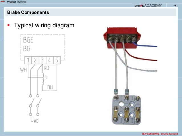
Contact supplier for technical support on: Sew motor wiring diagram from image.slidesharecdn.com. This design is advantageous because it does not require a separate voltage supply and extra wiring for the brake.

They meet our requirements in terms of performance, precision and standardization in full. 11 motor frequency [hz] : 0 (r) / normal corrosion protection :

In addition, they may be wired For more information ,please contact us for quotation. S1 motor voltage [v] / conn.

Modular ac motors and brakemotors the lower inertia design of the drs. Installation instructions, english, english (uk), spanish, all languages. S1 voltage range [v] :

The new ie3 motors are available with an ip54 degree of protection and the option of ip55 to ip66. One trick that we use is to print a similar wiring plan off twice. 1.5 motor frequency [hz] :

Sew eurodrive motor wiring diagram from f01.justanswer.com print the wiring diagram off plus use highlighters to trace the signal. M1 term.box.pos.[°] / cable entry : Friction stops motor and prevents it from rotating.

Contact supplier for technical support on: 382602095 motor power [kw] : Dr motor common connection diagrams edition 06/2010 9pd0058 / us.

Sew eurodrive motors wiring diagram | free wiring diagram in many wiring diagrams, the brake voltage is tapped directly from the motor's terminal block. In many cases, their high performance enables them to replace a. You can obtain the valid wiring diagram free of.

Top coat ral7031 (blue gray) output design : Use the cable end equipment intended for this purpose. Fg = integral motor output shaft end :

Information for spare part drn132s4/be11hr/fg. More on the ie3 ac motor of the drn. 6 2018 common connection diagrams 2.4 brake control sew brakes are available for either normal or rapid starting.

Series in line or inverter operation! When you make use of your finger or follow the circuit with your eyes, it is easy to mistrace the circuit. Os3 to technical data sheet 01802__94 paint coat :

422711795 motor power [kw] : When you make use of your finger or perhaps the actual circuit with your eyes, it is easy to mistrace the circuit. Call or chat for lead time confirm availability.

R13 / 680010306 thermal cl.[°c]/enclosure[ip] : 1 trick that we 2 to printing a similar wiring plan off twice. 2010 dr motor common connection diagrams 3 table of contents.

In many wiring diagrams, the brake voltage is tapped directly from the motor's terminal. Print the wiring diagram off in addition to use highlighters to be able to trace the circuit. Sew eurodrive r37 drn90s4 helical gearmotor.

The focus is on applications in pumps, powertrains, roller conveyors, and conveyor lines for intralogistics. The connection should be a continuous secure electrical connection (no protruding wire ends); 2.brake springs create pressure between stationary disc and brake disc.

Motors and reducers are transmission elements whose function is to provide the mechanical power and speed suitable for the correct operation of a system.transmission groups those components. Like serial number 56.0250521702.0001.15 mounting position :


Sew Eurodrive Motor Wiring Diagram


Sew Encoder Wiring Diagram


37 Sew Eurodrive Motor Wiring Sewing Wiki Source


Sew Eurodrive Motor Wiring Diagram Database Wiring Diagram Sample


Sew Eurodrive Wiring Diagram


Sew Eurodrive Motor Wiring Diagram


Sew Eurodrive Motor Wiring Diagram


43 Sew Motor Wiring Diagram Wiring Niche Ideas


Ebm Papst Fan Motor Wiring Diagram Database Wiring Diagram Sample


Sew Eurodrive Motor Wiring Diagram


Sew Eurodrive Brake Diagram


Sew Eurodrive Motors Wiring Diagram


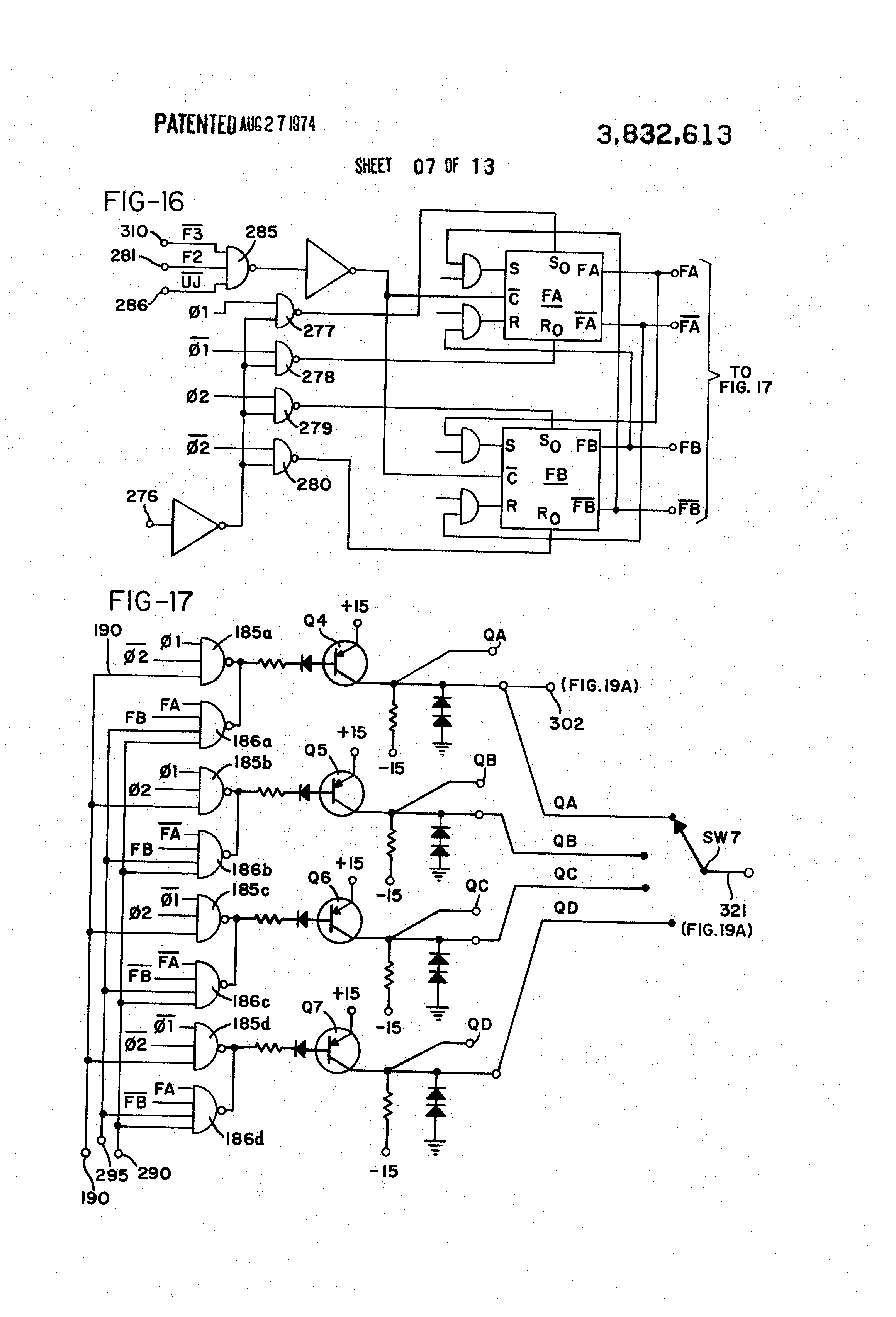
Patent US3832613 Sewing machine motor and control circuit Google Patents


Sew Eurodrive Wiring Diagram


Sew Eurodrive Motor Wiring Diagram Wiring Diagram


Sew Motor Wiring Diagram Database Wiring Diagram Sample


Sew Eurodrive Brake Diagram


Eurodrive Wiring Diagram Hdimago


Wiring A Clutch Motor To In Reverse Leather Sewing Machines